When we talk about input to the microcontroller unit, which may or may not be user input, it's not just ON/OFF switches or Push Buttons. In fact there are different methods for collecting data either from a user or the environment. According to the requirements, you can expect a user to press some button, toggle a switch, enter a username/password e.t.c. while various types of sensing devices are used to detect changes in the environment which will be discussed in my future posts. Today I am going to briefly introduce you to Keypad interface with the 8051 microcontroller. I have noticed many students having problem with this so I have tried my best to keep it as simple as possible while you will try your best to concentrate and understand it once and for all.
KEYPAD
Keypad is an input device and don't get confused by the name because it is nothing but a keyboard. So now we are definitely talking of many buttons which can serve as a keyboard for the user to input some data to our microcontroller. However, it can be of different shapes and sizes. For instance
 |
| 3x3 NUMERIC KEYPAD |
 |
| 4X4 HEX KEYPAD |
These are just two cases. We can have it in many other shapes. The key point here is to understand the story behind it and only then will you be able to tackle any type of keypad for interfacing. So let's move forward.
Here is the secret behind every keypad:
"Internally, each button of a keypad is nothing but a PUSH button (switch)"
Surprised? So was I when I found how simple it was. It means that if you open up any keypad, let's say 4x4 HEX Keypad as shown above, you'll witness something like
 |
| KEYPAD INTERNAL STRUCTURE |
As you can see, it has FOUR COLUMNS and FOUR ROWS (thus 4x4). In theory, pressing a particular button will simply connect the corresponding ROW - COLUMN lines and that's it. I mean that's exactly how a keypad actually works. A button doesn't know what it represents (1,2,3 e.t.c.). Similarly a keypad has no idea what each of its buttons represent because it's just a simple circuitry for many buttons at one place.
Now we can practically consider our 4x4 HEX KEYPAD as
 |
| 4x4 HEX KEYPAD (PRACTICAL) |
If we say 4x4, then it will definitely have four columns and four rows (as shown). It is clear now, from the internal structure information, that if you press button '5' then R2 and C2 will be shorted (connected). But then at the same time the most important question comes to mind.
Who exactly tells the microcontroller that it was button '5'?
Because we know now that it was just a PUSH button and we also know that it won't shout '5' when we press it so the microcontroller can hear it. So where does the magic happen?
The answer is as simple as it can be: Program Code.
It is the code itself that will monitor everything. It has to detect a button press and interpret the result. So interfacing a keypad to a microcontroller unit is purely a programmer's kind of thing because everything related to keypad is handled by the code. It's like creating something out of nothing and that's the beauty of it.
8051 KEYPAD INTERFACE
Before moving any further, let me revise a basic concept about INPUT/OUTPUT PINS of 8051 microcontroller. Consider the following circuit
If you configure the PIN as HIGH (INPUT) and read it, there are two possibilities
8051 KEYPAD INTERFACE
Before moving any further, let me revise a basic concept about INPUT/OUTPUT PINS of 8051 microcontroller. Consider the following circuit
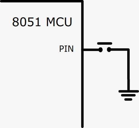 |
| PUSH BUTTON INTERFACE USING SINGLE PIN |
If you configure the PIN as HIGH (INPUT) and read it, there are two possibilities
- It will read as LOW if button is pressed (connected to ground)
- It will be HIGH if button is not pressed.
I think that's simple enough to understand. The same thing happens when you connect the button in the following way.
 |
| PUSH BUTTON INTERFACE USING DOUBLE PINS |
However you have to do the following for getting the same result as in the previous case
- Declare PIN1 as HIGH
- Declare PIN2 as LOW
This way, PIN2 acts as a 'ground' and PIN1 will read as LOW when the button is pressed otherwise HIGH. It is important to be very clear on this point as I will be using it for keypad reading.
Here is hardware connection diagram for keypad interface with 8051 microcontroller
 |
| 8051 KEYPAD INTERFACE |
That's it. The interfacing rule is simple enough.
You need to connect each pin of the keypad to UNIQUE pins of the 8051 microcontroller.
The rest is handled by the program code which I am going to briefly explain right now (finally).
KEYPAD INTERFACE CODE
It will be inconvenient to explain each step of the program code. I will rather prefer explaining it generally so you know exactly how to deal with any keypad. However, I have properly commented the program code (can be downloaded from the link given below) which will help you understand it quickly.
Reading from a keypad is called SCANNING because you have to check all the keys. Here are the basic steps for scanning a keypad.
- Select a ROW for scanning
- Scan each COLUMN in the selected ROW for key-press
- If key-press is not detected, move to next ROW and repeat the process
This way, we start from the first key and go all the way to the last one and then start over. This process repeats until a key-press is detected and that's where we move on to determining which key was pressed but that's another story. First let me explain how to implement SCANNING in terms of programming.
ALL PINS AS HIGH
First you need to declare all related PINS as HIGH. I will use the above connection diagram to graphically explain this step. Note that I have used PIN state (HIGH or LOW) instead of PIN number.
 |
| ALL PINS DECLARED AS HIGH |
SELECTING A ROW
Configure the corresponding PIN as LOW for selecting a particular ROW. For example, we will make the following PIN LOW for selecting first ROW (R1)
 |
| SELECTING FIRST ROW FOR SCANNING |
SCANNING COLUMNS
Simply check the values of PINS that are connected to COLUMNS. We already declared the PIN as HIGH in the first step so it will read as HIGH (1) if button is not pressed otherwise LOW if pressed. For example, if button '2' is pressed then we will get the following output which can be detected easily.
 |
| OUTPUT WHEN BUTTON '2' IS PRESSED |
You can check all the keys in this fashion i-e by scanning ROWS and COLUMNS and this process goes on until a key-press is detected. The microcontroller does it so quickly that it can never miss a key-press. A user can press a button in the first ROW when the microcontroller has just started to scan the second ROW but the good thing is that it will get back to the first row with the blink of an eye so you don't have to worry about that.
DETERMINING VALUE
This is the most important step and a bit tricky so I will try to keep it as simple as possible. Let me put your programming skills to test. Consider an array like
XYZ [ ] = { 'A', 'B', 'C', 'D', 'E', 'F', 'G', 'H', 'I' } ;
You also know that arrays always have indexes starting from zero, thus we have
XYZ [ 0 ] = 'A'
XYZ [ 1 ] = 'B'
XYZ [ 2 ] = 'C'
XYZ [ 3 ] = 'D'
XYZ [ 4 ] = 'E'
XYZ [ 5 ] = 'F'
XYZ [ 6 ] = 'G'
XYZ [ 7 ] = 'H'
XYZ [ 8 ] = 'I'
Now consider a 3x3 KEYPAD as shown below
 |
| 3x3 KEYPAD (ACTUAL) |
If I number the keys in order of scanning then I get the following layout. Note that I am kind of giving an index number to each button.
 |
| 3x3 KEYPAD (INDEXES) |
Now in the program, I can start a counter from ZERO and increment it as I walk through each key. Whenever a key-press is detected, the counter represents the index value at that stage. Of course, I will have to RESET the counter when I start over. If I use this counter value as an index to the array XYZ (mentioned above) then I get the corresponding value.
For example, if button 'E' is pressed then counter will have a value of '4' and thus
XYZ [ counter ] = 'E'
It is interesting to note how one thing relates to another. You might have noticed that you can shuffle the data in the array for an entirely different type of keypad arrangement. But you don't have to do that and confuse your end-user because a user expects 'E' at the output when he/she presses 'E' on the keypad so it's your job to keep it that way.
I have attached an example code so you can understand it more clearly. I have used a Seven Segment Display as output for displaying the key pressed. This keypad is available in Proteus Library but you can also design your own by placing and connecting PUSH buttons in the same manner as explained above.
 |
| KEYPAD INTERFACE PROTEUS SIMULATION |
That's the end of it. I think this is more than enough for now and I hope that you have got the idea. Feel free to ask if you have any confusion or problem following this article because I may have missed something or enclosed something big in a very small nutshell.
This ZIP package contains the following files
- C Language Code
- Compiled HEX file
- Proteus Design File
You can use all these files at your will but remember that they are for the sake of understanding the concept. You have to know what's going on and then it won't hurt if you just copy/paste but if you do it without caring about understanding, well all I can say is that it's not good for development.
Nice work...... Everything is perfect .. can easily learn this ... Keep it up .. :)
ReplyDeleteThanks :)
Deletegud work.. keep it up ... :)
DeleteGood explanation. Very easy and straight forward.
DeleteThank You Rizwan Ullah :)
Deleteu r realy awsome bro.. Allah bless u..:)
DeleteThanks for appreciating Aamir :)
Deleteu r welcome bro..:)
Deletein what way u have enter unsigned char keypad[ROWS * COLUMNS] = { 0x30, 0x6D, 0x79, 0,
ReplyDelete0x33, 0x5B, 0x5F, 0,
0x70, 0x7F, 0x7B, 0,
0, 0x7E, 0, 0 };
plz expain
I have explained these values in my previous article here
DeleteThose are HEX values for the corresponding LED arrangement in the Seven Segment Display. In other words, they represent the graphical 0,1,2,3 and so on.
ReplyDeletewhere is the c programming
ReplyDeleteYou can find it in the included ZIP package.
ReplyDeleteThat is really great job...thank you very much
ReplyDeleteYou're welcome :)
Delete