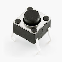
It is necessary for every system to have proper user interface - which makes it user friendly and easy to operate. For instance, imagine using your computer without the monitor (display), keyboard or mouse? It's not even possible to operate it without these essential components as they help you either in entering data (input) to the PC or seeing the results on screen (output). Similarly, an embedded system (the one involving microcontrollers such as 8051 in our case) also require input/ouput devices to be user friendly. A switch can act as an input device to the microcontroller unit (MCU) and this post is all about interfacing/connecting it to the 8051 MCU.
SWITCHES
Switches come in many different shapes and sizes. The main idea or function is to either enable or disable something by simply turning it on/off. Thus it acts as an input device that users can use to control certain parts of the system. Below are the most common switches that you will come across
 |
| Push Button |
 |
| DIP (Dual in-line Package) Switch |
 |
| ON-OFF Switch |
In circuit diagrams, a switch is generally represented by
 |
| Switch Symbol |
After examining the Switch Symbol, I think it is quite clear how a switch actually works. It closes (connects) or opens (disconnects) a circuit. The Push Button behaves in the same fashion as it closes the circuit as long as you keep holding it in pressed state.
8051 SWITCH INTERFACE
You can connect a switch to 8051 MCU using different configurations but the basic functionality remains the same. Always remember this cool fact that the user is never concerned about the actual implementation. He/she just wants something to turn ON when the switch is ON and vice versa OFF. As for you, you can handle it in many different ways. For example, you can connect a switch with 8051 MCU in the following ways (check the captions for comments)
 |
| GOOD - Safe to use |
 |
| FAIR - Can be used without much consideration |
 |
| POOR - too much current to the MCU |
These are the conventional methods of switch interface that you will find around in the internet. The good news is that at least they work. There are certain configurations that you need to avoid and must never use. For instance, have a look at these
 |
| VERY POOR - circuit is SHORTED when Switch is ON |
 |
| SERIOUSLY? Circuit SHORTED again |
Now how about this one that I am thinking of?
 |
| AWESOME - Safe to use |
It looks quite simple and still works effectively. The tricky part is that turning ON the switch will actually generate a LOW signal (connected to ground) but you can use that to your advantage as discussed in the program code below.
SWITCH INTERFACE CODE
Here is the C language code for the Switch Interface with the 8051 microcontroller. I have also used an LED in this example. If you don't know how to interface LED to 8051, you must check this article here. You can download the source code as well as the compiled HEX file from the link given below.
 |
| SWITCH Interface C Language Code |
Let me explain the code in a step wise fashion
- PIN1.0 is renamed as sw using #define directive (for convenience)
- Similarly PIN1.1 is renamed as led (LED is connected to this pin)
- sw is declared as input pin (for reading switch status)
- led is declared as output (for driving LED on/off)
- while( 1 ) is used to force MCU indefinitely work on this single task
- if ( !sw ) statement is true only if switch is ON (sw = 0 and !sw = 1) and thus led will glow
- Otherwise led will stay OFF
The same code simulated in Proteus looks like this (Proteus design file is also included in the package for your convenience)
 |
| Proteus Simulation |
This concludes the topic for today. I hope that after reading this post, you have at least some basic idea of using a switch with the 8051 microcontroller. If you have ANY question, suggestion, or feedback please feel free to share in the comments section. Furthermore, do check my previous posts for more help.
This ZIP package contains the following files
- C Language Code
- Compiled HEX file
- Proteus Design File
You can use all these files at your will but remember that they are for the sake of understanding the concept. You have to know what's going on and then it won't hurt if you just copy/paste but if you do it without caring about understanding, well all I can say is that it's not good for development.
Plz produce a next button to go to the next lesson......
ReplyDeletethanx
That's a bit confusing in this context :)
DeleteDid you mean
(A) Create a "NEXT" button using 8051?
(B) Include "Previous" and "Next" buttons in my articles?
what does the red and blue dots beside the diodes and parts of the micro-controller stand for.
ReplyDeleteRed means HIGH or ON
DeleteBlue means LOW or OFF
good explanation for beginners.
ReplyDeleteThank you :)
Deletewhat is the name of switch ? how can i get it from proties
ReplyDeleteIt's called DIP (Dual-in-line) switch.
Deletehow i can start any process with a single push button press... in 8051 please reply me on my email adress usama.love86@gmail.com
ReplyDeleteYou can interface that Push Button to a PIN and then listen to it. For example
Deletewhile( buttonNotPressed );
---
code for process
---
Now controller will be stuck in this loop unless you push that button. You can also achieve this using interrupts, which is normally a better approach.
I want to interface 2 switches. How to do it???
ReplyDeleteConnect them at two different PINS and program them accordingly.
DeleteThank you :)
ReplyDelete